LM3914 VU Meter Circuit – Visualize Your Sound! Vu meter wiring diagrams » wiring diagram
Understanding audio levels and visual representation is crucial in various applications, from music production to broadcast engineering. VU meters, or Volume Unit meters, provide a convenient and intuitive way to monitor the strength of an audio signal. These meters display the average signal level, allowing users to avoid clipping and distortion, and ensuring optimal sound quality. This post examines the principles behind VU meters and explores examples of implementation. The implementation and circuitry can be simple or complex to suit any user's purpose.
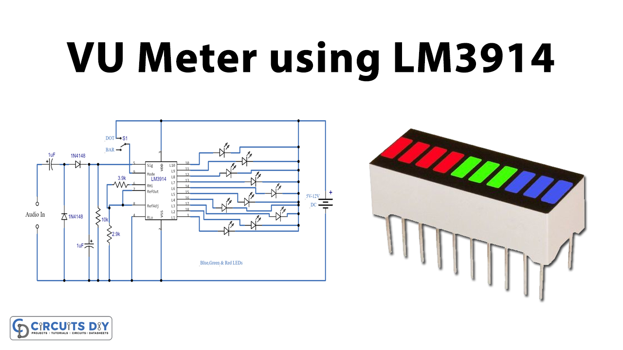
Fox Delta's Simple VU Meter with LM3914

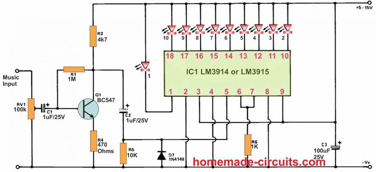
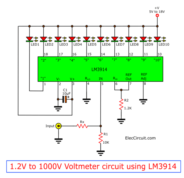
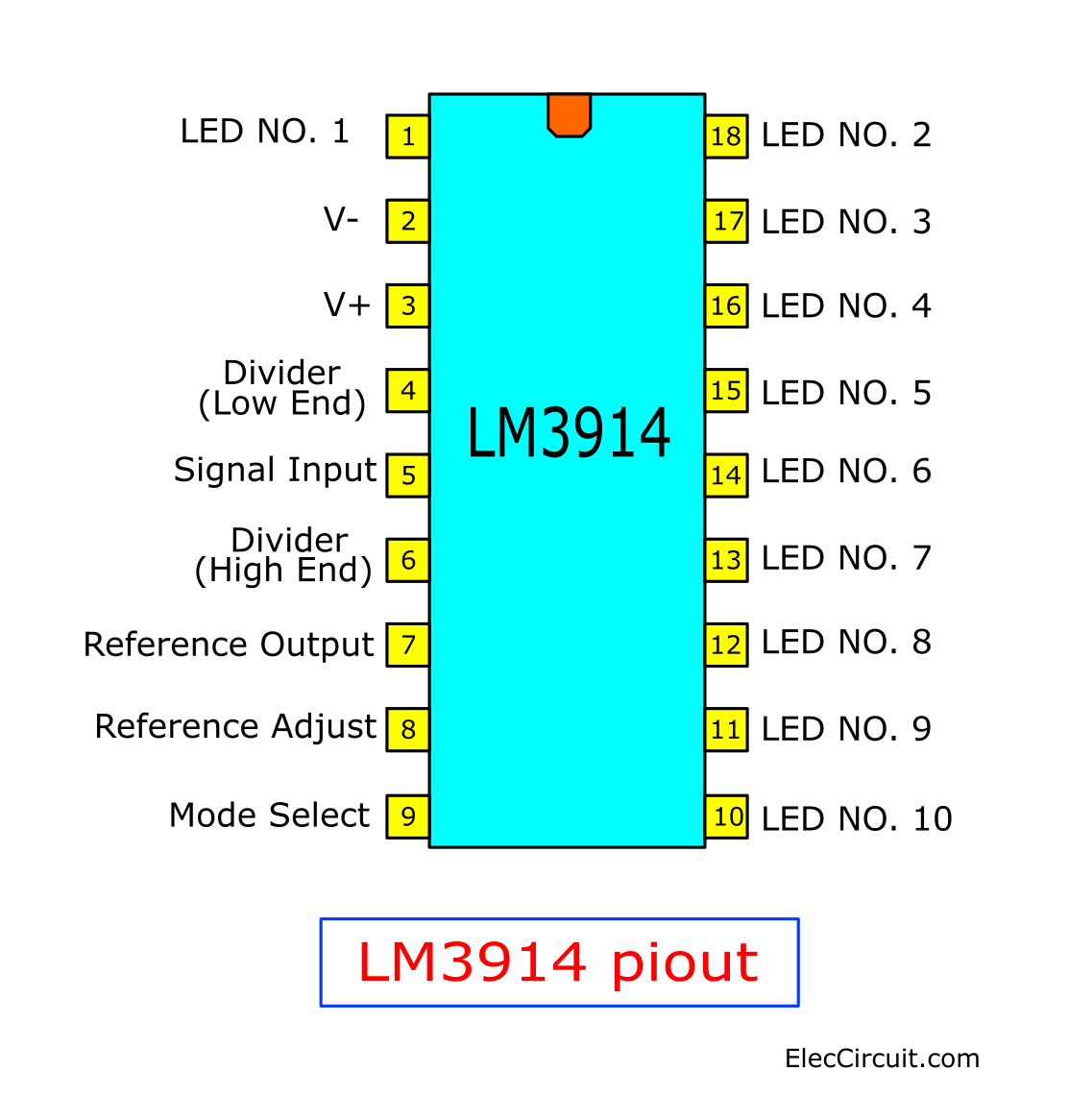
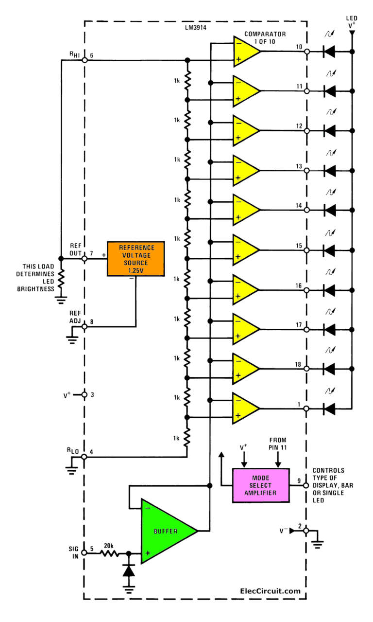
Fox Delta School Projects presents a simplified approach to building a VU meter using the LM3914 integrated circuit. The LM3914 is a monolithic integrated circuit that senses analog voltage levels and drives ten LEDs, providing a visual representation of the input signal strength. This design emphasizes simplicity and ease of construction, making it an excellent learning project for electronics enthusiasts and students. The components required are readily available, and the circuit is relatively straightforward to assemble. A key advantage of using the LM3914 is its built-in LED driver, which simplifies the design and reduces the number of external components needed. By adjusting the input voltage range of the LM3914, the VU meter can be customized to display different signal levels. This flexibility makes it suitable for various audio applications. The circuit typically involves connecting the audio signal to the input of the LM3914, setting the reference voltage using resistors, and connecting the LEDs to the output pins. The LEDs light up sequentially, indicating the audio signal strength. The brightness of the LEDs can be adjusted by changing the resistor values in the circuit. This provides a visual indication of the audio level, allowing users to monitor and adjust the audio signal accordingly. Moreover, the Fox Delta project serves as an excellent educational tool, demonstrating the practical application of integrated circuits in audio signal processing. The components are inexpensive and the circuit has very little power demand. An important note about these circuits is that the power source must be DC, not AC.
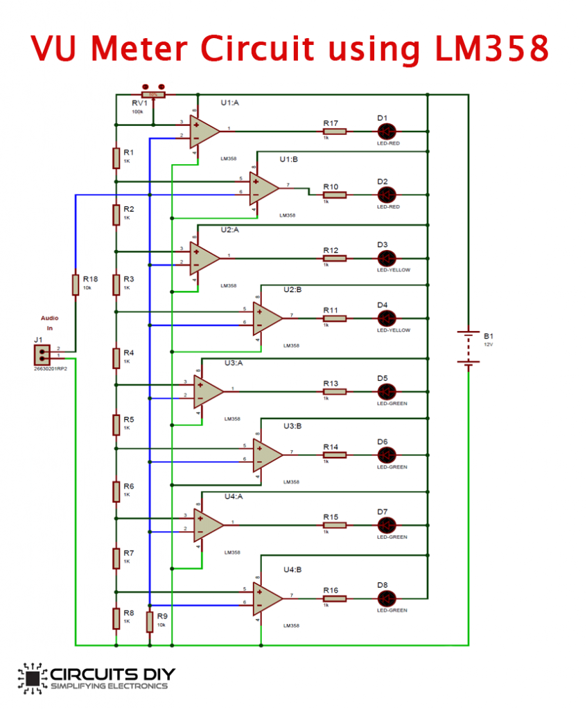
VU Meter Circuit Diagram using LM358

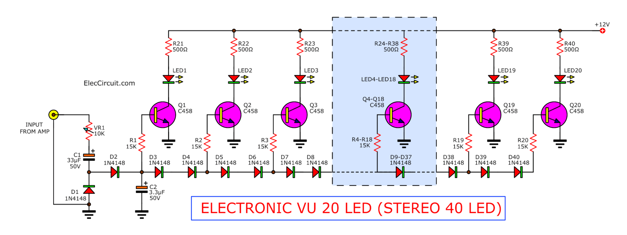
Circuits-DIY.com provides a VU meter circuit diagram that utilizes the LM358 operational amplifier. The LM358 is a low-power, dual operational amplifier that can be used to amplify and process audio signals. This circuit uses the LM358 to rectify and amplify the audio signal, which is then fed to a series of LEDs to provide a visual representation of the audio level. The circuit typically includes a rectifier to convert the AC audio signal into a DC voltage, an amplifier stage to boost the signal, and a voltage divider network to set the reference levels for the LEDs. The LM358’s versatility and low power consumption make it a popular choice for audio applications. The circuit is designed to be responsive to the audio signal, with the LEDs lighting up progressively as the signal strength increases. This provides a clear visual indication of the audio level, allowing users to monitor and adjust the signal accordingly. This approach provides a more sensitive audio level representation than the LM3914 solution. Furthermore, the circuit design allows for customization and fine-tuning to meet specific audio monitoring needs. By adjusting the component values, the sensitivity and response time of the VU meter can be optimized. This flexibility makes it suitable for a wide range of audio applications, from home audio systems to professional recording studios. The implementation is a bit more complex but provides better audio control. The LM358 also works with DC current and the component values should be noted before construction.
If you are looking for Led Vu Meter Circuit Diagram With Pcb Layout - Wiring Diagram you've visit to the right page. We have 25 Pics about Led Vu Meter Circuit Diagram With Pcb Layout - Wiring Diagram like Electronic Circuit Diagrams: LM3914 VU Meter, Lm3915 Vu Meter Circuit Diagram and also Electronic Circuit Diagrams: LM3914 VU Meter. Here you go:
Led Vu Meter Circuit Diagram With Pcb Layout - Wiring Diagram
 wiring.ekocraft-appleleaf.com
 VU Meter Circuit Diagram One Transistor 6 LEDs - TRONICSpro
 pcb-design.pages.dev
 Fox Delta School Projects:: A Simple VU Meter Using LM3914
 www.foxdelta.net
 meter vu lm3914 schematic simple using projects fm click view full gr next circuit circuits
Led Vu Meter Circuit Lm3914 – Artofit
 www.artofit.org
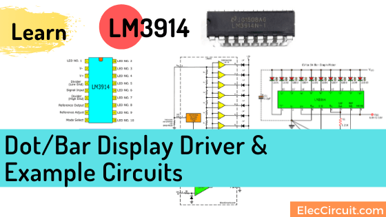
 LM3914 Datasheet Dot/Bar Display Driver | VU Meter Circuits
 www.eleccircuit.com
 lm3914 circuit voltmeter vu 2v circuits 1000v datasheet voltage eleccircuit scale full driver adjustable
LM3914 Datasheet Dot/Bar Display Driver | VU Meter Circuits
 www.eleccircuit.com
 lm3914 pinout circuits datasheet eleccircuit
LED VU Meter Circuit Using Transistors Or IC | ElecCircuit.com
 www.eleccircuit.com
 transistor transistors circuits eleccircuit
Electronic Circuits And Projects: How To Make An LED VU Meter Using LM3914
 circuitdigest.blogspot.com
 meter vu circuit led lm3914 electronic circuits projects using simple arduino circuitdigest make an how diy choose board
Vu Meter Circuit Diagram
 circuitlistadrienne.z13.web.core.windows.net
 Audio Level Meter Circuit - VU Level Meter Under Repository-circuits
 www.next.gr
 meter circuit level audio vu diagram sound circuits full analog gr next above size click
Adâncitură Rahat Buruiană Simple Led Vu Meter Circuit Zener Diode
 cristor.dz
 Lm3914 Vu Meter Circuit Diagram
 guidediagrampredict.z21.web.core.windows.net
 Simple Led Vu Meter Circuit Diagram - Circuit Diagram
 www.circuitdiagram.co
 LM3914 Datasheet Dot/Bar Display Driver | VU Meter Circuits
 www.eleccircuit.com
 lm3914 meter vu datasheet circuits eleccircuit block
Fox Delta School Projects:: A Simple VU Meter Using LM3914
 www.foxdelta.net
 meter vu lm3914 gajjar fm nina radio kit leds
Electronic Circuit Diagrams: LM3914 VU Meter
 circuitdiagramfree.blogspot.com
 vu meter lm3914 circuit diagram schematic audio pin led circuits de article electronic ic
Transistor Vu Meter Circuit
 schematicstretched.z14.web.core.windows.net
 LM3914 Datasheet Dot/Bar Display Driver | VU Meter Circuits
 www.eleccircuit.com
 lm3914 stereo system eleccircuit circuits datasheet lighting behavior ic2 ic1 r2
LM3914 VU Meter | Circuit Diagram
 www.circuitdiagram.org
 lm3914 meter vu circuit battery led sound audio activated diagram indicator switches sequential circuitdiagram
Simple VU Meter Circuit | Electronic Circuit Projects, Bar Displays
 br.pinterest.com
 Vu Meter Wiring Diagrams » Wiring Diagram
 www.organised-sound.com
 LM3914 Datasheet Dot/Bar Display Driver | VU Meter Circuits
 www.eleccircuit.com
 lm3914 vu circuits datasheet driver eleccircuit
Electronic Circuit Diagrams: LM3914 VU Meter
 circuitdiagramfree.blogspot.com
 vu lm3914 meter
Lm3915 Vu Meter Circuit Diagram
 www.circuitdiagram.co
 Electronic VU Meter By LM3914 And LM3915
 www.eleccircuit.com
 vu meter lm3914 lm3915 pcb stereo electronic led circuit hold layout peak eleccircuit components main figure component form using
Electronic vu meter by lm3914 and lm3915. Lm3914 datasheet dot/bar display driver. Electronic circuits and projects: how to make an led vu meter using lm3914